Well, today things really began to get nasty! The gas generator section was relatively clean, at least compared to the power turbine and gearbox interior. Yet once again lots of pictures.
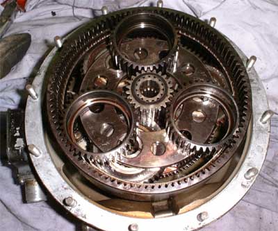
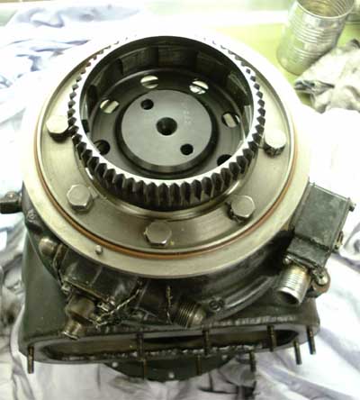 Thats a view of the output shaft side
of the reduction gear box assembly. At the inside of the cup gear there are wedges visible that form the outer member of the overrunning clutch (ratchet-type). This disengages the mechanical linkage to the main engine
gearbox once the main engine is started up. At the 7 oclock position the reduction gear lubrication fittings are located, at the 9 oclock position there is the high pressure oil inlet for the oil jets for lubrication of the
high-speed bearings (I think).
Thats a view of the output shaft side
of the reduction gear box assembly. At the inside of the cup gear there are wedges visible that form the outer member of the overrunning clutch (ratchet-type). This disengages the mechanical linkage to the main engine
gearbox once the main engine is started up. At the 7 oclock position the reduction gear lubrication fittings are located, at the 9 oclock position there is the high pressure oil inlet for the oil jets for lubrication of the
high-speed bearings (I think).
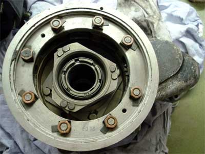 Here the other member of the
overrunning clutch is shown. This housing as well allows attaching of some accessories that are driven by the outer gear ring shown in the picture above.
Here the other member of the
overrunning clutch is shown. This housing as well allows attaching of some accessories that are driven by the outer gear ring shown in the picture above.
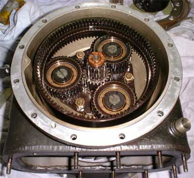 Finally opened! Some brute force was
required to get the gear box apart. What came to sight was rather surprising. I would have expected some epicyclic gear, but this is a differential one! The drive shaft from the free power turbine directly drives
two sun gears, one of 23 teeth and one of 15 teeth. The smaller set of planetary gears (next to the turbine) is suspended on bearings that are mounted to a flange of the gearbox casing (fixed gears). The outer ring
gear with 99 teeth runs completely free on the three planetary gears in the opposite direction of the sun gear. So far nothing really unusual.
Finally opened! Some brute force was
required to get the gear box apart. What came to sight was rather surprising. I would have expected some epicyclic gear, but this is a differential one! The drive shaft from the free power turbine directly drives
two sun gears, one of 23 teeth and one of 15 teeth. The smaller set of planetary gears (next to the turbine) is suspended on bearings that are mounted to a flange of the gearbox casing (fixed gears). The outer ring
gear with 99 teeth runs completely free on the three planetary gears in the opposite direction of the sun gear. So far nothing really unusual.
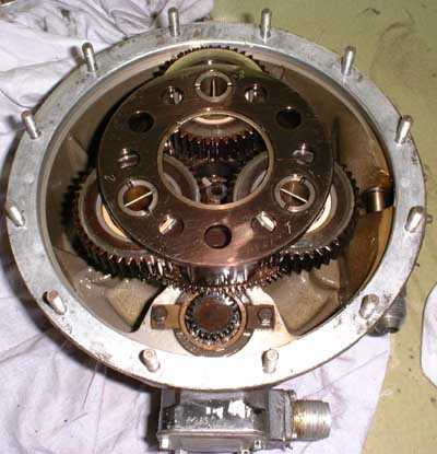 The second set of planetary gears
(shown in this picture) is suspended by bearings that are attached to the output shaft. They run in the other half of the ring gear, separated by a recess. Now something funny happens: as the two sun gears have
different numbers of teeth , the free; larger set of planetary gears will rotate around the sun gear at a rate that is determined by the difference of the teeth counts of both sun gears and the
number of teeth of the ring gear. With a setup like this it is possible to build gears with a reduction ratio of 100:1 and more. This gear has a reduction of 14.25:1
The second set of planetary gears
(shown in this picture) is suspended by bearings that are attached to the output shaft. They run in the other half of the ring gear, separated by a recess. Now something funny happens: as the two sun gears have
different numbers of teeth , the free; larger set of planetary gears will rotate around the sun gear at a rate that is determined by the difference of the teeth counts of both sun gears and the
number of teeth of the ring gear. With a setup like this it is possible to build gears with a reduction ratio of 100:1 and more. This gear has a reduction of 14.25:1
 Here all the gears are placed on the
output shaft side of the gearbox to show the arrangement of all the components. You should see it turn as its really amazing, but unfortunately I havent got a camcorder to record a short clip of it.
Here all the gears are placed on the
output shaft side of the gearbox to show the arrangement of all the components. You should see it turn as its really amazing, but unfortunately I havent got a camcorder to record a short clip of it.
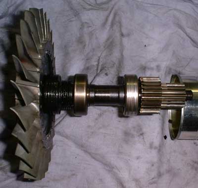 Thats the free power turbine along
with suspension, seals and sun gears on the shaft. I decided to remove this wheel due to a little much radial play in the suspension (at least in my opinion). It turned out to be a good decision because the condition of the
second (deep groove ball) bearing is at least questionable. There seems to be evidence for rotation of the outer bearing member in the bearing seat, which would mean that the bearing must have been at least partially
blocked. After cleaning of the bearing it still revealed a little rough feeling, in a bicycle I probably wouldnt mind, but in this high-speed equipment Id rather look out for a replacement. The roller
bearing at the turbine side after some cleaning feels much better than the other one, so I will probably leave it in place.
Thats the free power turbine along
with suspension, seals and sun gears on the shaft. I decided to remove this wheel due to a little much radial play in the suspension (at least in my opinion). It turned out to be a good decision because the condition of the
second (deep groove ball) bearing is at least questionable. There seems to be evidence for rotation of the outer bearing member in the bearing seat, which would mean that the bearing must have been at least partially
blocked. After cleaning of the bearing it still revealed a little rough feeling, in a bicycle I probably wouldnt mind, but in this high-speed equipment Id rather look out for a replacement. The roller
bearing at the turbine side after some cleaning feels much better than the other one, so I will probably leave it in place.
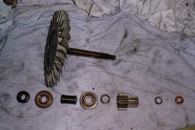 Once again the shaft components, this
time in sequence of assembly. On top the free turbine wheel with hub and shaft as an integral unit, below from left to right: second labyrinth seal inner member, roller bearing, spacer tube,
ball bearing, spacer washer, sun gear assembly, locking washer, locking clip, nut. All the labyrinth seals are badly crusted with oil carbon deposits.
Once again the shaft components, this
time in sequence of assembly. On top the free turbine wheel with hub and shaft as an integral unit, below from left to right: second labyrinth seal inner member, roller bearing, spacer tube,
ball bearing, spacer washer, sun gear assembly, locking washer, locking clip, nut. All the labyrinth seals are badly crusted with oil carbon deposits.
 Thats the exhaust volute as shown
from the reduction gear side. This space behind the volute is (or should be ??) cooled by compressor delivery air. The mounting orientation of the engine is such that the coked area points down. This means that
lubrication oil must have leaked out of the gear box and puddled in this area. This oil can only creep through the free turbine shaft seal that would be almost impossible except the gear box is
flooded with oil so that the level is higher than the turbine shaft and then the engine is shut down. As long as theres compressor air pressure between the two sealing faces of the labyrinth seal, it would be virtually
impossibly for the oil to find a way through the seals.
Thats the exhaust volute as shown
from the reduction gear side. This space behind the volute is (or should be ??) cooled by compressor delivery air. The mounting orientation of the engine is such that the coked area points down. This means that
lubrication oil must have leaked out of the gear box and puddled in this area. This oil can only creep through the free turbine shaft seal that would be almost impossible except the gear box is
flooded with oil so that the level is higher than the turbine shaft and then the engine is shut down. As long as theres compressor air pressure between the two sealing faces of the labyrinth seal, it would be virtually
impossibly for the oil to find a way through the seals.
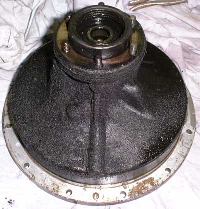 And thats a really nasty thing, its the
exhaust volute side of the turbine garbox housing. The mounting flange is sandwiched between the rear gearbox housing and the exhaust volute assembly. Part of the oil that has coked there has condensed to
some kind of asphalt, I wonder if this engine has ever seen a synthetic oil. On the other hand, in this cavity shouldnt be any oil at all. After I discovered this mess I decided my hands were dirty enough for a sunday
afternoon and went for a piece of cake... Have to buy new wire brushes anyway before I can continue this ;-)
And thats a really nasty thing, its the
exhaust volute side of the turbine garbox housing. The mounting flange is sandwiched between the rear gearbox housing and the exhaust volute assembly. Part of the oil that has coked there has condensed to
some kind of asphalt, I wonder if this engine has ever seen a synthetic oil. On the other hand, in this cavity shouldnt be any oil at all. After I discovered this mess I decided my hands were dirty enough for a sunday
afternoon and went for a piece of cake... Have to buy new wire brushes anyway before I can continue this ;-)
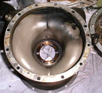
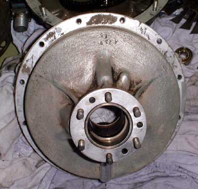 Thats what it looked like a whole
afternoon of cleaning afterwards. Theres a fitting on the exhaust volute housing that accepts high pressure oil as used for lubricating the gas generator bearings. This oil is routed through some bores to a nozzle orifice
that is located inside of this component. This nozzle is drilled under a shallow angle in regards to the turbine shaft so that the oil is injected into the roller bearing located next to the power turbine wheel. The
rear (ball) bearing is splash lubricated by oil contained in the gear box.
Thats what it looked like a whole
afternoon of cleaning afterwards. Theres a fitting on the exhaust volute housing that accepts high pressure oil as used for lubricating the gas generator bearings. This oil is routed through some bores to a nozzle orifice
that is located inside of this component. This nozzle is drilled under a shallow angle in regards to the turbine shaft so that the oil is injected into the roller bearing located next to the power turbine wheel. The
rear (ball) bearing is splash lubricated by oil contained in the gear box.
In between I drilled out the broken bolts at the exhaust flange and already re-tapped the threads (mainly removing the thread material remaining from the broken bolts). During this work I discovered a crack in the exhaust volute close to a place that has been repaired already. I will grind off any material that projects from the previous repair attempt and give this part to my welding wizard to get it repaired. The crack isnt severe and I guess the engine would run perfectly with it, but once I have discovered it, it surely must be repaired ;-).
I soaked the free power turbine ball bearing in kerosine for a prolonged time and flushed the fluid several times, and fortunately this bearing feels much better now. Maybe the bearing has only been very dirty. So I will sipmly put it back in again and see if it performs well. All the bearings throughout the engine are standard ISO seizes but they are of a very high quality with machined brass cages and probably very close tolerances. So I will avoid replacing them as long as it isnt definitely necessary. When it gets a little warmer outside I will use the high pressure cleaner to blow out all the metal chips and remains from retapping of the exhaust flange holes out of the sxhaust housing and then Ill reassemble the power turbine and gearbox section. Then the fuel and lubrication pump will be inspected.
From a very kind similarly minded individual from Italy I will receive a copy of the maintenance guide for this engine so I will get to know a little more about the thermodynamic properties of this engine soon. Unfortunately this manual is written in Russian language (what else should I expect...) but a friend of mine could probably help me with translating the important sections of it. Well, maybe its time to learn a least the cyrillic alphabet ;-).
Some time has passed since my last update to this part of my web site. And some things have evolved since then, partially good partially not so much... After some hassle and some promises by friends that they will repair the crack in the exhaust volute that werent fulfilled, I finally decided to have a try at welding the crack myself. So I got myself the right filler material and started the job with my neat little TIG welder. At first it seemed to turn out fine, but everytime I got the crack closed and let the volute cool down, a new crack close to the old one evolved. You wont need an oracle to guess how the story ended - with a big, nasty hole in the volute. I know, I should have heated the whole workpiece before welding but I simply havent got the tools to do this. About this time I got into contact with more and more individuals who privately own TS-21 units, just like me. Actually it seems that these turbines are ubiquitious in Germany and even more so in Poland. We now have got a good source for these engines in Poland and they are sold for comaparably little money.
This way I learned to know a guy in Germanys east, close to the Polish border. He has got a few of the TS-21s as well and also had them running, though only for short periods. And he had a runaway condition with two of the engines which resulted in a complete destruction of the turbine sections.
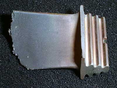 Thats what all of the turbine blades
looked like after the aforementioned incident.
Thats what all of the turbine blades
looked like after the aforementioned incident.
His fault was that he oriented the engine the wrong way round, so the oil drain of the gear box pointed to the top while it should have been at the bottom. So the gear box couldnt drain its oil and was flooded completely. There was not much problem with this condition as long as the engine kept on running and the oil/air seals were pressurised. But after shutdown, all the oil above center level of the gear box drained through the labyrinth seals into the combustor housing area. Now you can guess what happened during the next start. The engine started up seeminly as usual. but after the oil got heated up high enough, it lit and burned in the rear section of the combustor with flames leaping through both turbine wheels. At this stage, the engine was completely out of control and accelerated beyond safe limits while also the turbine section was overheated. So all blades threw its tips. It was mere luck that - due to its thermal inertia - the turbine disks stayed intact. A burst of them wouldnt have been contained by the turbine shroud. This way the result was only a (minor) loss of property (namely the engine) and - at that time - the question why the turbine quit. It was not before another one of these turbines threw its guts that this certain person comprehended what was going on. If we had been into contact before, this mess could probably have been avoided. Anyway, this way I got to get an almost mint exhaust volute to replace my damaged one. It has only a mild layer of sputtered turbine blade material on its inner surface that can be removed with a piece of hard wood without damage to the base metal. Ive also got the complete gear box with the bearings in somewhat better condition than those of my engine. So next will be cleaning, assembly of the free turbine section from the best condition parts of both engines and finally some re-painting. And finally the reunion of the gas generator and the gearbox.
In between Im about to get some documentation on the TS-21 engine in German and English so I hope Ill be able to gather some more useful information. Rumors tell that the engine actually is way more powerful than the approx. 85hp as claimed by the russian manual. This would match the look and feel of the whole unit, especially if compared to other engines in the 80hp regime. Ive been told by several sources that this engine would produce about 180hp if pushed to the limit. But as long as I havent got definite figures, Ill rather accept the 85hp than dreaming of something unproven or possibly even dangerous.
What is certain by now is that the engine will throttle quite happily and is running very calm at idle. There isnt even a load required at the power takeoff as long as the engine is idling. The bad news is that the original fuel control unit has got only two throttle settings, namely idle and full power. Of course theres the acceleration controller that prevents an overtemp but otherwise theres only some adjustment screws for limiting the absolute maximum conditions. In its original purpose of starting the Tumansky RD-11 main engine (or whatever type they use) of the MiG-21 or MiG-23 aircrafts, the FCU is controlled by a dual pressure sensitive switch assembly, controlled by compressor delivery air. The switch with the lower threshold operates if the combustor pressure is high enough to allow the labyrinth seals to work properly. This switch opens (or closes in case of shutdown) the dual solenoid valve to admit oil and fuel to the engine and energise the FCU motor. The FCU initially is in full power mode, accelerating the engine rapidly. Eventually the second pressure switch closes at a compressor delivery pressure that could be considered the engine design pressure. This switch energises the idle solenoid at the FCU, reducing the fuel injection pressure to a value to just prevent flameout of the combustor. Now engine RPM and hence compressor delivery pressure starts to decrease until the second pressure sensitive switch opens again. This goes on and on and causes the gas generator of the TS-21 to oscillate around its design pressure. This governing mechanism isnt very elegant and will stress the hot section componens much more than a linear governor (due to the heat cycling) but it is as simple as can be. And its probably very reliable. What should I say - bullet proof Russian engineering - or KISS - keep it simple stupid ;-p
The good news is that the simple idle solenoid of the FCU can be modified to operate as an adjustable bypass valve. This way the engine can be controlled by the current fed through the solenoid coil. However, it will work the other way round, i.e. no current means idle or even shutdown, maximum current corresponds to maximum injection pressure. I will start this modification as soon as the enigine is in one piece again.
To be continued.