µ-Turbine
I must be crazy! Completely crazy. So many projects at the time and I cannot resist to start a new one. But this one I had on my mind already for about one year though I didnt do much to realise it until recently I obtained the Rotor of a 3K-Warner KP31 turbocharger. This is the smallest unit currently in production for automotive use. The compressor has a diameter of only 33mm while the turbines size is 31mm. My idea is to build a turbine engine as small as possible for an amateur, by using a readily available rotor assembly that is. I dont want to go through the process of manufacturing these high-speed components due to safety reasons. By the way it would be much too difficult to design and machine such a small compressor wheel with sufficiently high efficiency. This engine isnt necessarily intended to be used as a propulsive device but it might be equipped with some kind of alternator to produce electricity as well. The first design is a turbojet, though.
And now lets have a look at some of the components!
07/13/2001
 Wow, is this going to be a small
turbine engine?
Wow, is this going to be a small
turbine engine?
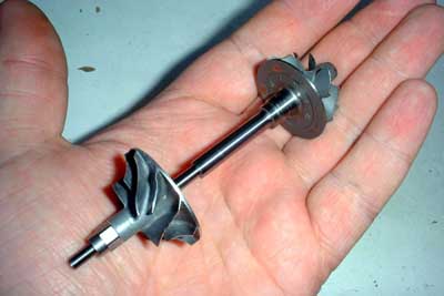
Here you get an idea of the size of this rotor, though my paws arent small either ;-).
This picture has been moved here from my turbine introduction page as I finally finished some of the additional components, though not too many yet.
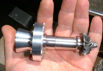
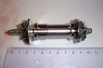 Thats the rotor assembled inside the
shaft tunnel. Thats all that has been (almost) finished so far. The scale on the ruler in this picture is in centimeters. The whole engine wont be much longer than about 12cm (less exhaust nozzle). To make the outer
casing I intend to use the can of one of those energy drinks. The total diameter will be slightly less than 53mm. Ill still have to figure out if its possible to reasonably manage a combustion within this small volume,
but if Im going for propane as fuel I think it will be feasible.
Thats the rotor assembled inside the
shaft tunnel. Thats all that has been (almost) finished so far. The scale on the ruler in this picture is in centimeters. The whole engine wont be much longer than about 12cm (less exhaust nozzle). To make the outer
casing I intend to use the can of one of those energy drinks. The total diameter will be slightly less than 53mm. Ill still have to figure out if its possible to reasonably manage a combustion within this small volume,
but if Im going for propane as fuel I think it will be feasible.
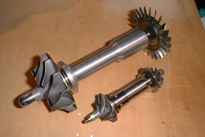 Heres the KP31 rotor compared to a
KJ66 rotor assembly. The whole assembly so far weighs just 120g. I hope Ill be able to build the whole engine to weigh no more than 300g. But this will mainly depend on the weight of the NGV and the combusor
liner as these components will need to be made of stainless steel or nickel-base alloy.
Heres the KP31 rotor compared to a
KJ66 rotor assembly. The whole assembly so far weighs just 120g. I hope Ill be able to build the whole engine to weigh no more than 300g. But this will mainly depend on the weight of the NGV and the combusor
liner as these components will need to be made of stainless steel or nickel-base alloy.
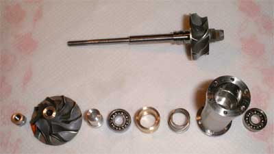 Thats all the components for this
engine so far (except the energy drink can). Most of the (machining) work consumed the shaft tunnel. It is made from stainless steel and has to be made to the closest tolerances. The front bearing is spring-preloaded and
is seated in an O-ring to dampen possible vibrations. This ring is located in a groove inside the shaft tunnel. Thats the reason of the step in diameter to the front of the tunnel. A brass bushing is used to apply the
spring force equally to the outer race of the front bearing. The bearings will still have to prove if they stand the exorbitantly high design speed of this engine of 210,000 rpm. They are special
low-noise high precision bearings intended to be used in hard disk drives. These bearings have got a higher radial play so they can be used with increased axial preload. Calculations have
shown that from the material strength point of view the bearings wont be stressed too much at this speed. What cannot be calculated easily is the effect of possible vibrations. Unfortunately
there dont seem to be hybrid bearings easily available in this size.
Thats all the components for this
engine so far (except the energy drink can). Most of the (machining) work consumed the shaft tunnel. It is made from stainless steel and has to be made to the closest tolerances. The front bearing is spring-preloaded and
is seated in an O-ring to dampen possible vibrations. This ring is located in a groove inside the shaft tunnel. Thats the reason of the step in diameter to the front of the tunnel. A brass bushing is used to apply the
spring force equally to the outer race of the front bearing. The bearings will still have to prove if they stand the exorbitantly high design speed of this engine of 210,000 rpm. They are special
low-noise high precision bearings intended to be used in hard disk drives. These bearings have got a higher radial play so they can be used with increased axial preload. Calculations have
shown that from the material strength point of view the bearings wont be stressed too much at this speed. What cannot be calculated easily is the effect of possible vibrations. Unfortunately
there dont seem to be hybrid bearings easily available in this size.
One design issue of this engine that differs from any other homebuild model aircraft gas turbine engine is that the outer case isnt a structural part of this engine. The compressor diffuser as well as the NGV will be bolted to the shaft tunnel which will consequently take the axial pressure force. The case will only need to stand the pressure radially. Many engine designs require reinforced cases due to cracking at the NGV mounts. This design wont have any such at the outside. So the case can be built as light-weight as possible. To prevent too much heat transfer from the NGV to the rear of the shaft tunnel a mica washer will be put in between.
The angles of the compressor diffuser vanes and the NGV are already calculated and some preliminary sketches are drawn. But to mill these two components Ill first need to upgrade the spindle motor of my little CNC mill. So further progress on this project will probably take some time. Once (if?) the engine is running I will publish the construction details here for download.
10/06/2001
Still little progress on the upgrade of my mill as one component is still missing. But Ive got my new CAM software, so at least here are a few pictures of the compressor diffuser and NGV as I calculated them. I hope they turn out this fine after machnining.
 Heres the diffuser. The vanes are
designed as slightly forward swept wedges that start at an angle of 21°. These vanes continue uninterruptedly through all the way of the axial deflection of the compressor delivery air. The opening angle increases
through this quarter-torus surface to compensate for the effect of the lesser flow path area increase the more the air turns axially.
Heres the diffuser. The vanes are
designed as slightly forward swept wedges that start at an angle of 21°. These vanes continue uninterruptedly through all the way of the axial deflection of the compressor delivery air. The opening angle increases
through this quarter-torus surface to compensate for the effect of the lesser flow path area increase the more the air turns axially.
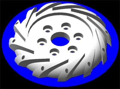 Heres a rendered picture of the
diffuser. I wish I already had it milled and it also looks this nice! The outer diameter is only 52.5mm and the total height is 8mm. Some of the twelve mounting holes (M2) will be used to
route fuel and oil supply lines into the engine.
Heres a rendered picture of the
diffuser. I wish I already had it milled and it also looks this nice! The outer diameter is only 52.5mm and the total height is 8mm. Some of the twelve mounting holes (M2) will be used to
route fuel and oil supply lines into the engine.
 This picture showes a drawing of the
NGV for the radial turbine wheel. In general it looks very similar to the compressor diffuser except the wedge-shaped vanes are swept in the other direction. The wheel entry angle of the hot gas will be 24° and the
nozzle area is calculated (or should I better say estimated...) to allow for a total gas velocity of 400m/s, regarding the narrowing effects due to the boundary layer.
This picture showes a drawing of the
NGV for the radial turbine wheel. In general it looks very similar to the compressor diffuser except the wedge-shaped vanes are swept in the other direction. The wheel entry angle of the hot gas will be 24° and the
nozzle area is calculated (or should I better say estimated...) to allow for a total gas velocity of 400m/s, regarding the narrowing effects due to the boundary layer.
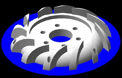 And again, the above design as a
rendered computer graphics. This machining will probably take a whole day due to the tough material involved (stainless steel or possibly, if my mill will do, Hastelloy). Yet I wonder if a
single end mill be sufficient or if Ill need a whole bunch of them to get this compnent finished. If I knew somebody with metal casting euqipment Ild probably just mill a sample out of plastics (or wax) to have
this part cast. The rear face can be machined easily afterwards on the lathe.
And again, the above design as a
rendered computer graphics. This machining will probably take a whole day due to the tough material involved (stainless steel or possibly, if my mill will do, Hastelloy). Yet I wonder if a
single end mill be sufficient or if Ill need a whole bunch of them to get this compnent finished. If I knew somebody with metal casting euqipment Ild probably just mill a sample out of plastics (or wax) to have
this part cast. The rear face can be machined easily afterwards on the lathe.
So much for now, I hope next time I add to this page there will be some more photos of real parts.
01/07/2002
I almost feel ashamed to put the date in here as so little has happened on this project since my last actualisation. This is mainly due to the fact that Im still waiting for the firmware upgrade for my mill. Its almost one year since the advertisement of the update and more than four months since I got the CAD/CAM software upgrade that actually should have been a package with the new firmware EPROM and the new machine driver. In a few days Ill be on a visit to ISEL and hopefully be able to set some things straight...
Yet after some difficulties I got some special custom made hybrid bearings suitable for this engine (thanks, Andy!):
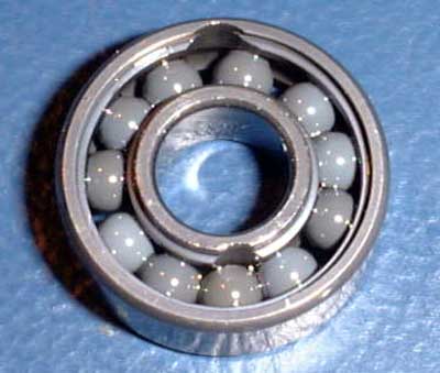 These bearings are full complement,
deep groove bearings with ceramic balls. There had a filling slot to be ground into each of the races to allow insertion of the balls. Yet filling in the balls is only possible if the outer race
is heated and the inner one is cooled so they expand vs. shrink to enlarge the play of the grooves. This way its impossible to lose a ball during operation, even if the two slots match in position together with a ball. The
races have been coated with some tungsten alloy to form a super-hard, wear-resistant surface. This way the bearings should almost last forever. At least with these special bearings I feel much more positive to taking the
engine to the RPM limit - that is if it will run at all ;-).
These bearings are full complement,
deep groove bearings with ceramic balls. There had a filling slot to be ground into each of the races to allow insertion of the balls. Yet filling in the balls is only possible if the outer race
is heated and the inner one is cooled so they expand vs. shrink to enlarge the play of the grooves. This way its impossible to lose a ball during operation, even if the two slots match in position together with a ball. The
races have been coated with some tungsten alloy to form a super-hard, wear-resistant surface. This way the bearings should almost last forever. At least with these special bearings I feel much more positive to taking the
engine to the RPM limit - that is if it will run at all ;-).
03/27/2002
I finally modified my mill with the new firmware and tool spindle motor. I already machined some componnts and it seems the accuracy got somewhat better than before. So came the day and it was time to mill a real 3D-component, namely the diffuser. After developing a clever milling strategy and generating the machine file (slightly less than 1MB which I consider quite small for a component like this), I started the mill for this four-hour job. And heres the result:
 Keeping in mind that this was the first
really complex 3D component I made on my mill, I consider the result quite acceptable. Yet some details went wrong, especially the fact that the base material that held the part in place during smoothing out the outer
surface was only about 0.1mm and so the whole workpiece vibrated a little. Somehow the postprocessor produced these deep cuts that werent part of the actual job. Anyway, Ill use this part and maybe later I might make
another one. I found out that processing time could still be reduced by about half an hour. I think for machining a part like this from solid with only a 2mm end mill and without high.speed machining equipment
(read: expensive ;-) within three and a half hours is quite acceptable. I dont think a Kamps style diffuser can be hand-made this fast. Next will be a real tough job, namely milling of the NGV. But first the mist lubrication
system would need to be attached to the mill.
Keeping in mind that this was the first
really complex 3D component I made on my mill, I consider the result quite acceptable. Yet some details went wrong, especially the fact that the base material that held the part in place during smoothing out the outer
surface was only about 0.1mm and so the whole workpiece vibrated a little. Somehow the postprocessor produced these deep cuts that werent part of the actual job. Anyway, Ill use this part and maybe later I might make
another one. I found out that processing time could still be reduced by about half an hour. I think for machining a part like this from solid with only a 2mm end mill and without high.speed machining equipment
(read: expensive ;-) within three and a half hours is quite acceptable. I dont think a Kamps style diffuser can be hand-made this fast. Next will be a real tough job, namely milling of the NGV. But first the mist lubrication
system would need to be attached to the mill.
04/06/2002
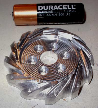
I decided to mill another diffuser, just to check out if my new milling strategy still saves some time, and yes, it does. This time I limited milling depth according to the base material thickness minus 0.5mm so theres always enough left to hold the diffuser firmly in place. Afterwards these 0.5mm are machined off on the lathe, thus opening the flow channels to the combustion chamber (still to be designed). I also machined the compressor housing, using the mill to make the inner parts as to precisely match the profile of the compressor wheel and the diffuser. The rest of the housing is machined on the lathe.
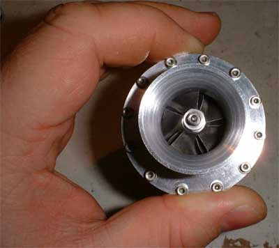 Heres a front view of the compressor.
Twelve M2 screws are used to mount the compressor housing to the diffuser, which has a M2 thread tapped into each of its vanes. Three of these tapped holes will be drilled out to accept the fuel and lubrication lines
as well as a combustor pressure probe port. Now that Ive got the final bearings in, it turned out that Ill need to make another compressor wheel spacer that is about 0.1mm longer than the current one. Since the whole
engine will be so small in size, the tolerances need to be very close as well.
Heres a front view of the compressor.
Twelve M2 screws are used to mount the compressor housing to the diffuser, which has a M2 thread tapped into each of its vanes. Three of these tapped holes will be drilled out to accept the fuel and lubrication lines
as well as a combustor pressure probe port. Now that Ive got the final bearings in, it turned out that Ill need to make another compressor wheel spacer that is about 0.1mm longer than the current one. Since the whole
engine will be so small in size, the tolerances need to be very close as well.
 I needed to grind the compressor
bearing seat a little larger since the bearing will be suspended in an O-ring to dissipate some vibration energy. This is required to avoid shaft oscillations at the fundamental resonance frequency. Hence there
needs to be play in the front bearing seat of a few hundredths of a millimeter. I also made a shaft reinforcment tube that goes between the bearings and allows tensioning of the shaft which increases its
resonance frequency as well. I hope all these measures are suitable to make the rotor assembly withstand up to 220,000 rpm.
I needed to grind the compressor
bearing seat a little larger since the bearing will be suspended in an O-ring to dissipate some vibration energy. This is required to avoid shaft oscillations at the fundamental resonance frequency. Hence there
needs to be play in the front bearing seat of a few hundredths of a millimeter. I also made a shaft reinforcment tube that goes between the bearings and allows tensioning of the shaft which increases its
resonance frequency as well. I hope all these measures are suitable to make the rotor assembly withstand up to 220,000 rpm.
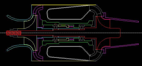
A long time has passed since the last update and little has happened since then, but finally I decided to draw a section of the whole engine so it will be easier to specify the dimensions of every component. It already helped me to find out that a few (not yet manufactured) components had errors in size of about 0.1mm. So heres the drawing (screenshot from my CAD desktop):
To be continued.