03/23/03 A few days ago I met with Andreas once again to discuss how to proceed on his project. Im almost finished with the full-automatic engine control system while he is busy improving his turbine engine. He is going to fit a complete new rotor with some components mad much more rigid and reliable. Also we decided that the current starting system is not reliable enough and way too heavy. So he will use a starter-generator, mounted directly to the engines main shaft. My task will be designing the control electronics to dirve this electronically commutated three-phase machine during startup and afterwards when it operates as a generator.
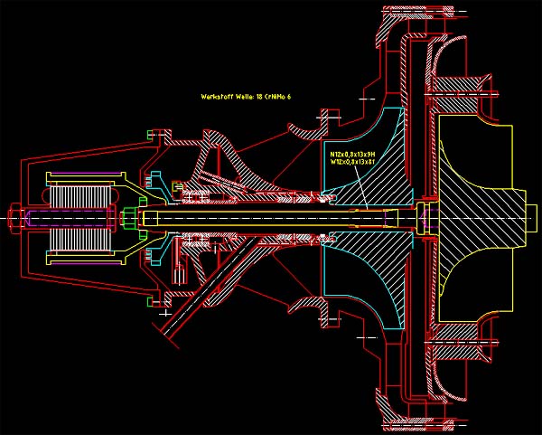 |
This is a screenshot from my CAD program that shows the rotor assembly of Andreass engine. At the left theres the starter-generator that is designed as an outside-revolving motor. To avoid bell oscillations, the magnetic reluctance ring will be reinforced by a pre-tensioned winding of carbon fibre rovings, soaked with resin. Since the magnets are on the inside surface of this ring, we wont need to worry about them flying off at the high speed rotation. At the right the two wheels are shown, isolated from each other by a heat shield and the compressor diffuser. Also a labyrinth shaft seal is placed here. The shaft arrangement is of the cantilevered type with all the bearings in front of the conpressor in a cool area. Due to the very small inducer hub diameter of the turbocharger radial compressor wheel, the bearing next to this wheel must be of the hydrodynamic type. No roller or ball bearings with a low enough thickness, suitable for this speed, are available. The bearing on the starter-generator end of the shaft is made of two angular-contact hybrid ball bearings which are axially preloaded against each other. This way axial loads are supported in both directions.
Now some photos of the engine components follow.
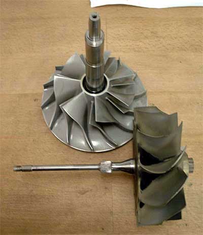
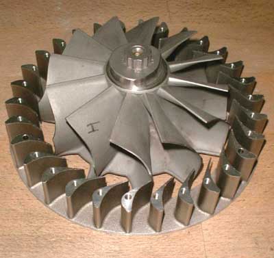
 Thats the turbine rotor, made from
KKK turbocharger spares. The compressor bore is enlarged to accept the thick shaft required for the cantilevered suspension arrangement. To prove the compressor hub is still strong enough, Andreas had the wheel
high-speed tested at MTU (Motoren und Turbinen Union). Slide measure for size comparison.
Thats the turbine rotor, made from
KKK turbocharger spares. The compressor bore is enlarged to accept the thick shaft required for the cantilevered suspension arrangement. To prove the compressor hub is still strong enough, Andreas had the wheel
high-speed tested at MTU (Motoren und Turbinen Union). Slide measure for size comparison.
 Once again the rotor components,
this time separated. Theres a spline machined to the turbine shaft to be able to transfer the considerable torque tot he main shaft and the compressor wheel. The part of the original turbine shaft thats left as a tie bolt is
astonishingly thin. But this has to stand only an axial load. Nevertheless this bolt will be kept stronger in the new rotor design
Once again the rotor components,
this time separated. Theres a spline machined to the turbine shaft to be able to transfer the considerable torque tot he main shaft and the compressor wheel. The part of the original turbine shaft thats left as a tie bolt is
astonishingly thin. But this has to stand only an axial load. Nevertheless this bolt will be kept stronger in the new rotor design
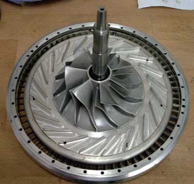 The compressor diffuser consists
of straight vanes and a set of flow straightening radial vanes at the circumference. It has about twice the diameter of the compressor wheel. Consequently the efficiency should be quite good.
The compressor diffuser consists
of straight vanes and a set of flow straightening radial vanes at the circumference. It has about twice the diameter of the compressor wheel. Consequently the efficiency should be quite good.
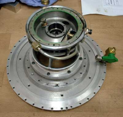
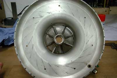 This and the following picture show
the compressor cover/bearing housing assembly. This is one of the most complicated parts of the whole turbine engine because it contains the complete lubrication system for the single hydrodynamic
and the two hybrid ball bearings.
This and the following picture show
the compressor cover/bearing housing assembly. This is one of the most complicated parts of the whole turbine engine because it contains the complete lubrication system for the single hydrodynamic
and the two hybrid ball bearings.
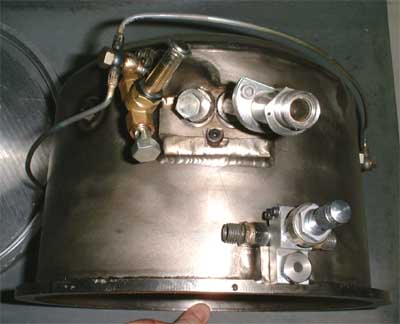 The combustor casing is welded
form solid machined and formed sheet titanium(!) components. Whats shown here is one of the spark plugs with the pilot burner fuel fitting and the fuel drain port in the lower right of the picture.
The combustor casing is welded
form solid machined and formed sheet titanium(!) components. Whats shown here is one of the spark plugs with the pilot burner fuel fitting and the fuel drain port in the lower right of the picture.
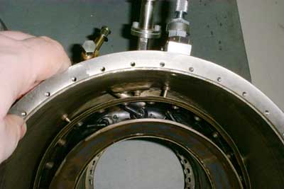 And thats a shot into the
combustor. The liner is of the vaporizing type and originates from a commercial APU. It has been donated by the manufacturer to support this project.
And thats a shot into the
combustor. The liner is of the vaporizing type and originates from a commercial APU. It has been donated by the manufacturer to support this project.
 Here the turbine NGV and a
turbine wheel that had been damaged upon machining are shown. The NGV ring has been spark eroded from solid inconel 718.
Here the turbine NGV and a
turbine wheel that had been damaged upon machining are shown. The NGV ring has been spark eroded from solid inconel 718.
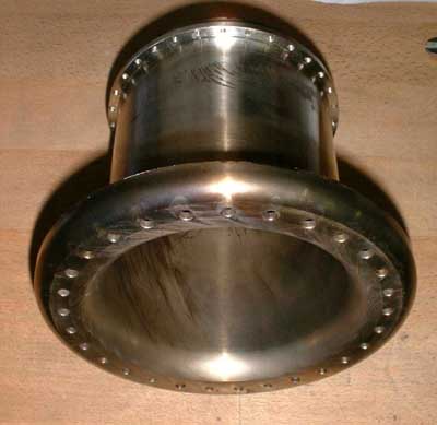 The turbine cover has also been
machined from solid inconel. A previous version, made from worked sheet metal, tended to warp during operation and caused turbine rubbing.
The turbine cover has also been
machined from solid inconel. A previous version, made from worked sheet metal, tended to warp during operation and caused turbine rubbing.
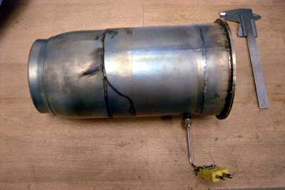 The thrust nozzle with an EGT
thermocouple has been attached to the engine to simulate the load of the free power turbine. The nozzle itself was used on a small commercial thrust engine and had been extended to better fit Andreass engine.
The thrust nozzle with an EGT
thermocouple has been attached to the engine to simulate the load of the free power turbine. The nozzle itself was used on a small commercial thrust engine and had been extended to better fit Andreass engine.
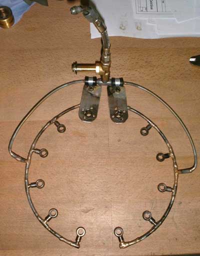 The fuel manifold supplies diesel
or kerosine to the twelve vaporiser sticks. To provide equal fuel quantities to all sticks, the fuel has to pass calibrated resirictor plates in each of the injectors.
The fuel manifold supplies diesel
or kerosine to the twelve vaporiser sticks. To provide equal fuel quantities to all sticks, the fuel has to pass calibrated resirictor plates in each of the injectors.
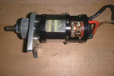 Thats the motor that Andreas used
to start his engine. It is a Plettenberg Dino and produces up to 2.5kW of mechanical power. It will be replaced by a brushless starter/generator system in the new design.
Thats the motor that Andreas used
to start his engine. It is a Plettenberg Dino and produces up to 2.5kW of mechanical power. It will be replaced by a brushless starter/generator system in the new design.