Williams Research WR24-7-2
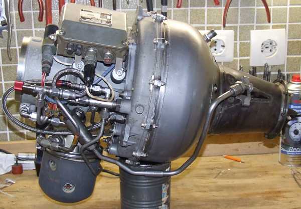
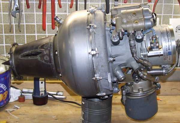
Once again I had the chance to acquire a relatively rare engine, the WR24-7-2 made by Williams Research, Michigan, USA.
The engine was chosen by Northrop to power their MQM-74C Chukar II aerial target drone (i.e. their only purpose was for being shot at...hard life ;-). Yet, this power plant was also used for testing of reconnaissance drones produced by other manufacturers, even if it later didnt come to fruition. The engine that I got originated from one of the latter applications.
The leading particulars of the WR24-7-2 are:
|
Calculations show that the engine will have a pressure ratio of around 5:1 and an air mass flow of 1.4 to 1.5kg/s. The gas temperature at the turbine stage entry will be around 980°C. Heres a link to a short lineup of the WR24s turbomachinery particulars.
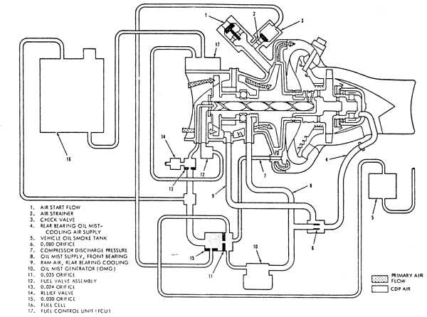 |
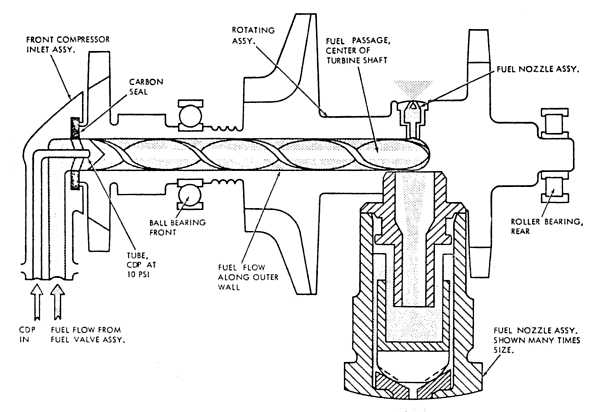
This sketch shows the basic layout of the engine (click the image for a higher resolution TIFF
version). The engineers at Williams Research found some very clever solutions for details to keep the engine as simple as possible while it requires minimum maintenance and can still be
manufactured at reasonable expenses. There are three peculiarities that distinguish this engine from most other small turbojets.
Firstly, theres the rotating atomizer that was introduced by Turbomeca of France but had been
pioneered for very small engines by Williams with the WR2. The advantage of this fuel injection
pinciple is that only a very low fuel pressure is required and that the atomisation over a wide RPM range stays close to perfect. The most serious disadvantage is that no shaft tunnel can be used
for the bearing arrangement and hence the engine casing becomes a structural member of the rotor suspension, requiring high precision on that component.
Secondly, and closely related to the fuel injection system, is the way the fuel is delivered to the engine. The Williams engineers used compressor bleed air to slightly pressurize the fuel cell in
order to feed the fuel to the engine-mounted fuel control unit. This completely eliminates the need for a pump.
And finally, the lubrication system is configured as a total loss system, running on a finely
atomized oil mist. A small oil tank is attached to the engine, containing round about 0.4 liters, and compressor bleed air is used in some kind of venturi arrangement to atomize the oil. The oil flow
is very low (specified to be less than 125 gramms per hour), and many big engines have higher losses through their labyrinths, even though they feature a return oil system.
The engine is specified to be recoverable after salt water immersion (of course only after shut-
and cooldown...) and is only supposed to be flushed and cleaned with different liquids and then test run to dry out the cleaning agents. For such a simple motor, thats a great advantage since its
not automatically a write-off if the drone has to go down over the sea (i.e. it runs out of fuel while operating as a target over water).
On the particular engine that I got, this cleaning procedure probably has not been carried out completely or in a timely manner, the result was some minor corrosion on the aluminium parts,
major corrosion on the magnesium alloy (probably...) axial compressor rotor and salty-oily deposits everywhere in the engine. Otherwise, the engine was in a very nice condition, yet I had to
tear it down completely to clean everything. And I wont do a job like this without my camera, so now some photos of the components are show (from intake to the exhaust...)..
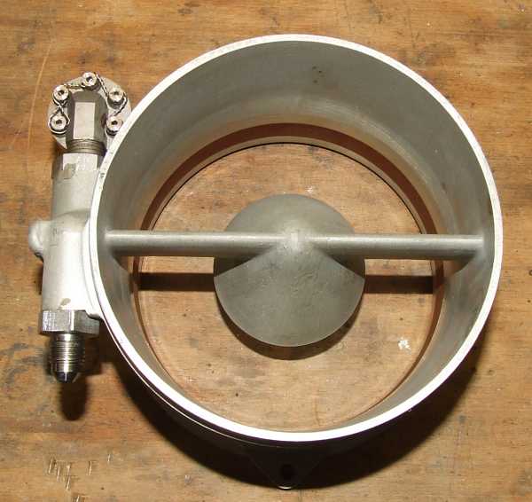 |
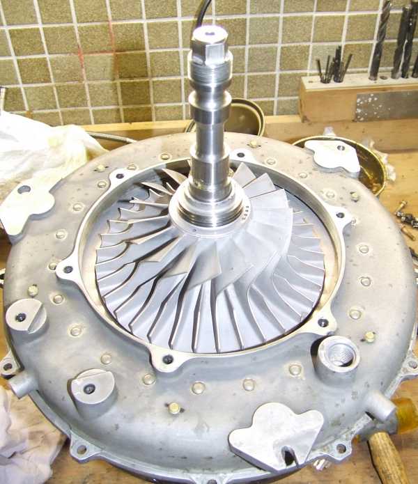
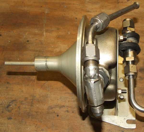
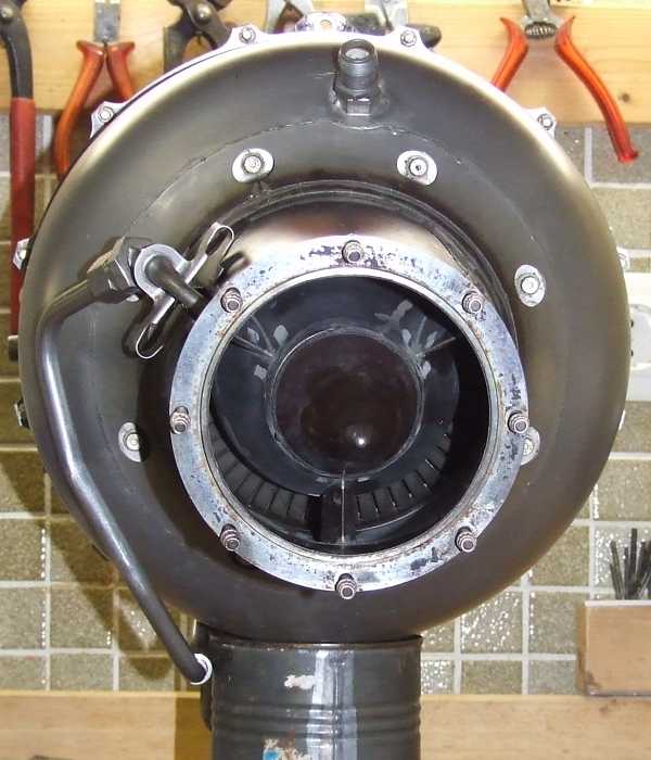
The intake with the fuel inlet and purge air fittings
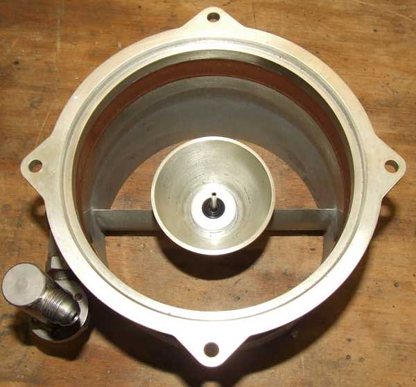 |
The area that shrouds the axial compressor is internally lined with a (brownish) polymer, thus permitting an interference fit with the axial impeller for very small tip clearance.
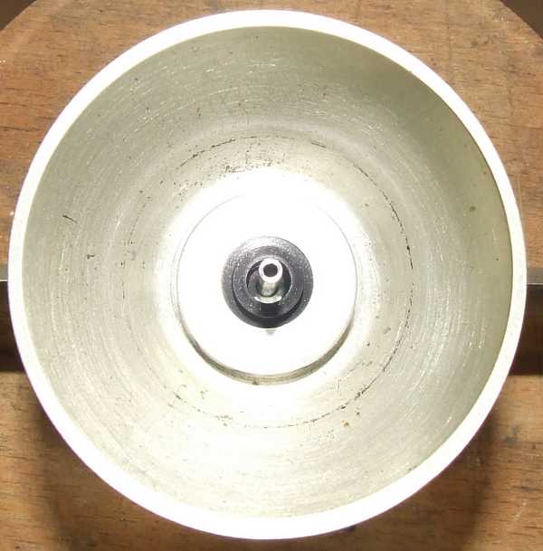 |
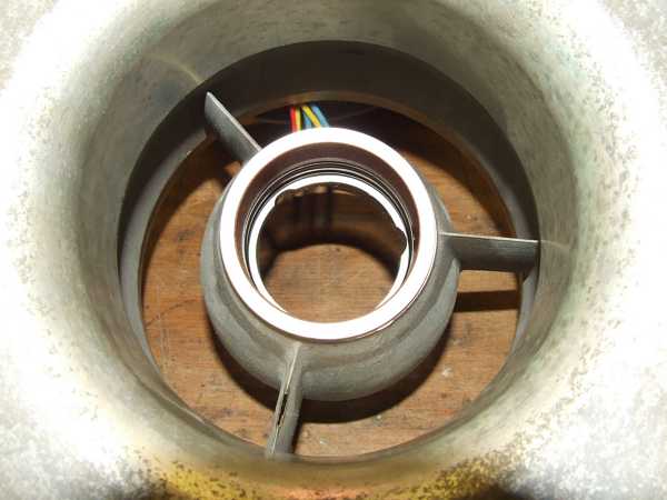
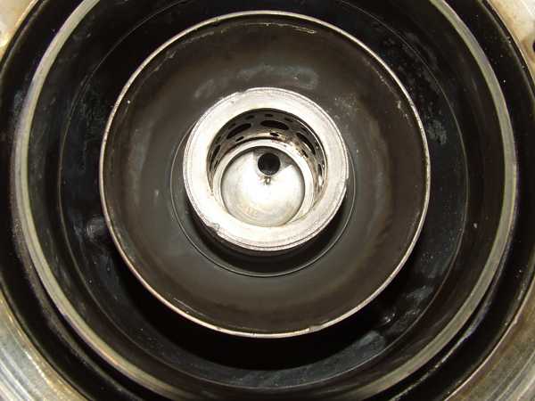
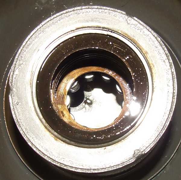
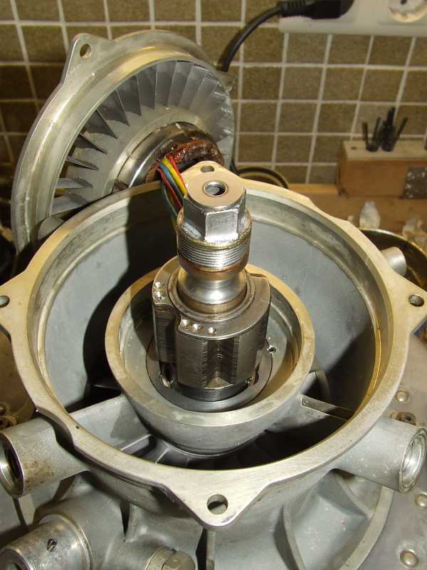
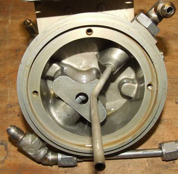
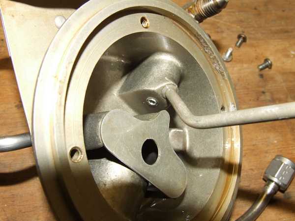
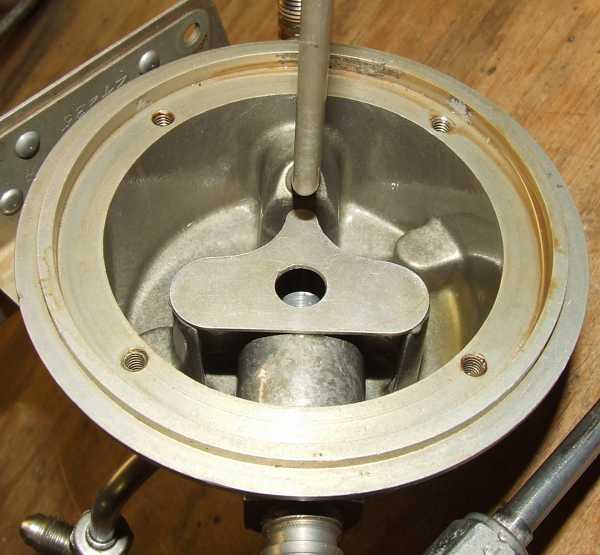
The center cone houses the carbon (graphite) seal that slides on a polished insert in the rotor shaft. Fuel enters through the annular orifice between the capillary tube and the graphite disc while the scavenge air is introduced through the tube. The engine manual didnt mention it but I guess the air is required to scavenge all fuel from the shaft upon engine shutdown and thus preventing the four injection nozzles from coking when the heat soaks from the hot engine components to the shaft.
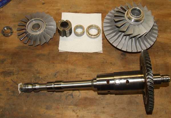 |
The components of the rotating assembly from top left to lower right: The shaft nut, the axial compressor impeller, the alternator rotor, a spacer, the compressor bearing, the radial compressor impeller (with another spacer more or less permanently attached to the rear of its hub), and finally the turbine wheel/shaft assembly with the roller bearing inner race riding on the short shaft end.
 |
Here a close-up of the spare axial compressor impeller that shows minor traces of corrosion but is generally still in acceptable shape. Its incredible how light-weight this component is, hence I assume its made of either magnesium alloy or even aluminium-lithium.
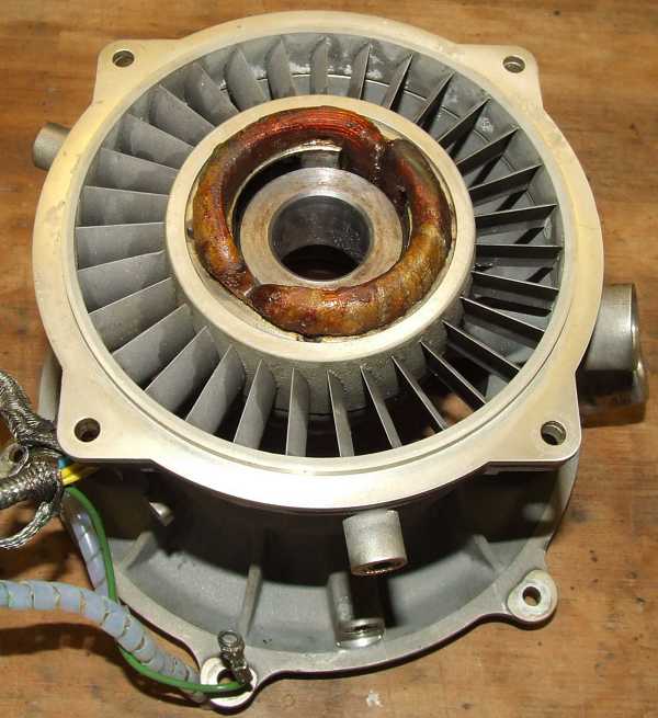 |
The alternators stator is located inside the axial compressor stator. The stator itself consists of a set of iron laminations that contain AlNiCo magnets to provide the bias field. the rotor only consists of laminations that close and interrupt the magnetic flow, thus producing an oscillating field that induces the voltage in the coils. This type of alternator is called switched reluctance machine. Since the AlNiCo magnets are susceptible to demagnetization if a too strong counter-field is applied, inside the stator a magnetic keeper has to be installed during disassembly.
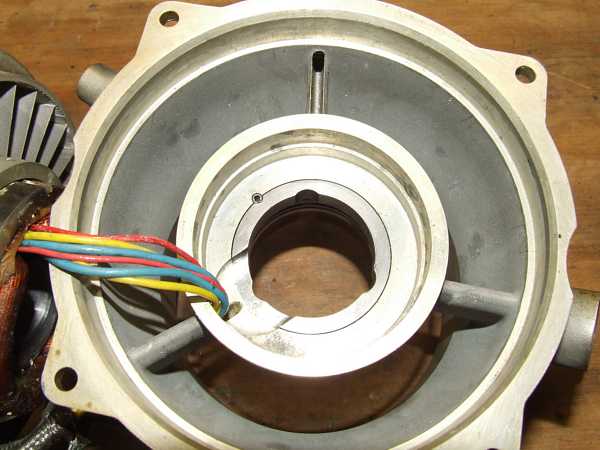 |
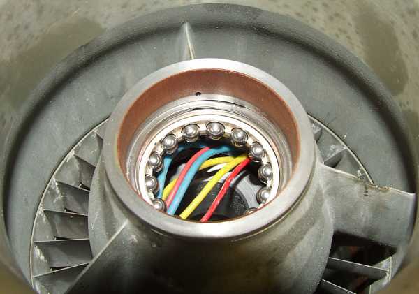
The wires of the alternator run through one of the three struts of the radial compressor cover. The other strut extracts first stage compressor bleed air (here in the 12 oclock position) to cool the turbine bearing, the third one (in the 4 oclock position) feeds the oil mist to the compressor bearing.
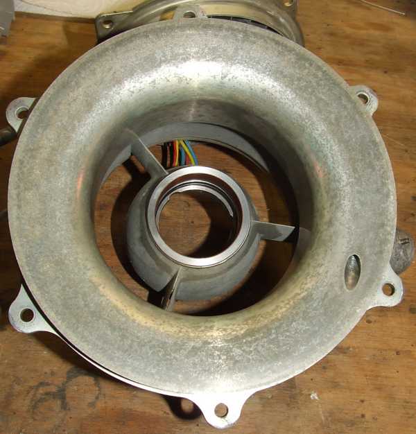 |
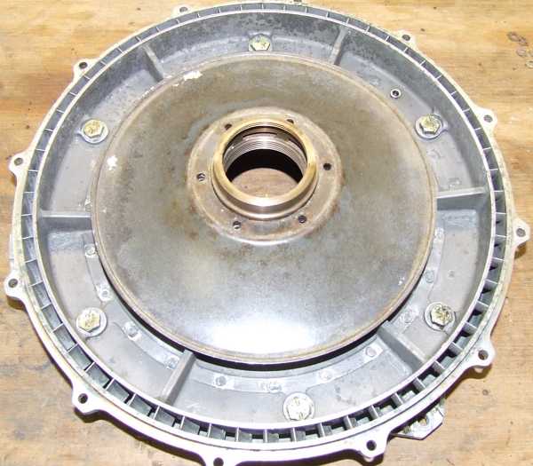
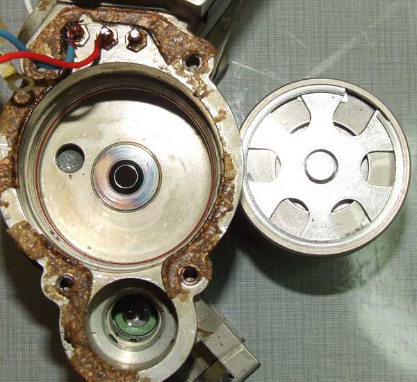
The rear of the compressor cover. Theres slight surface corrosion present but its nothing to worry about. Also the starting air nozzle is visible that directs compressed air into the radial section of the second stage compressor to spin up the engine to ignition speed (air impingement starter).
 |
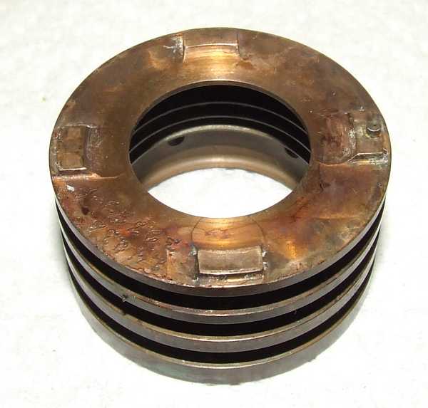
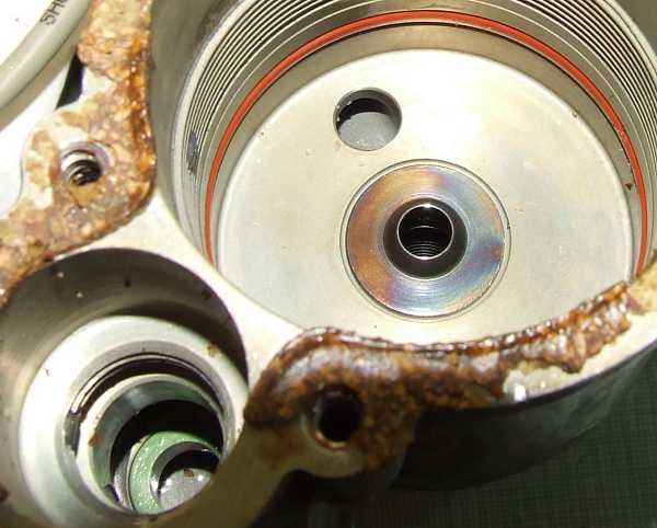
The compressor bearing seat contains two O-rings that prevent the outer race of the front bearing from rotating. Moreover, they act as vibration dampers. The labyrinth area is lined with a polymer coating to permit minimum clearance.
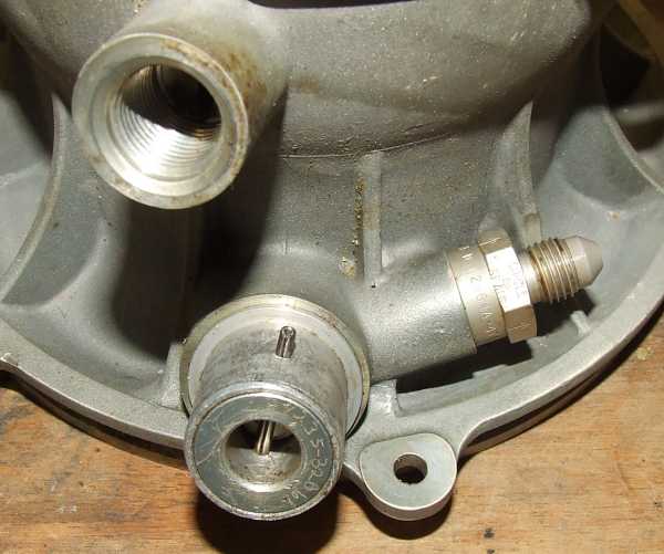 |
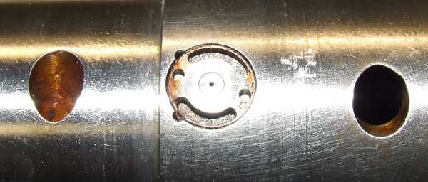
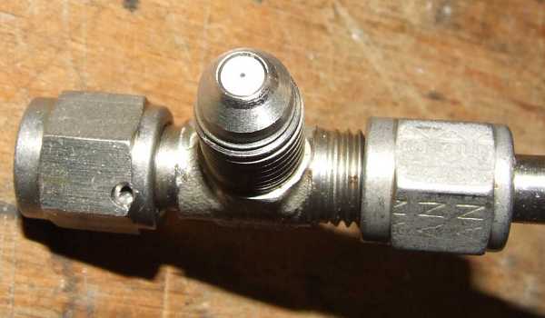
This is the starting air port that contains a check valve. To the right, some of the starting air is diverted to pressurize the oil mist generator and the fuel cell. Top left is the oil mist inlet for front bearing lubrication.
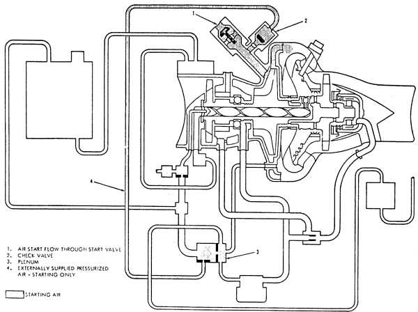 |
This sketch shows the starting air scheme and how it is diverted to supply the oilmist generator and to pressurize the fuel cell.
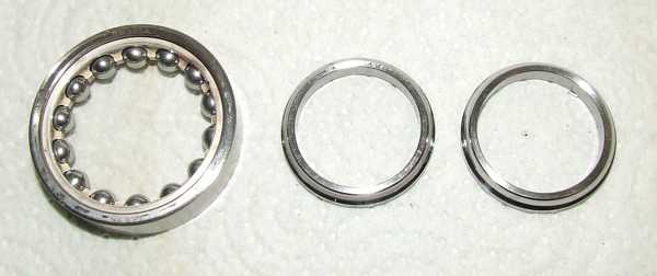 |
The front bearing is of the four-point contact type and is of the highest precision.
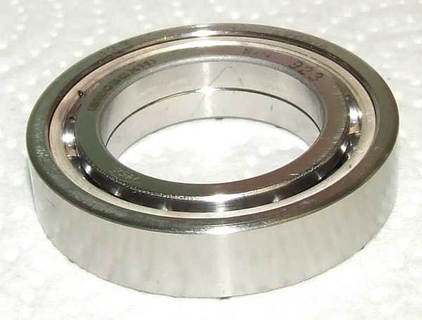 |
The split inner race has to be assembled in a certain orinetation. For this purpose, an arrow (V) has been etched over the two halves of the race to indicate the direction of the axial force. Upon assembly, the V has to be matched.
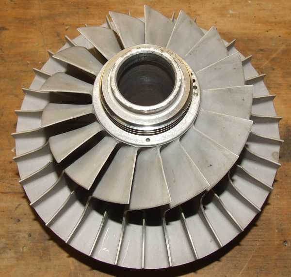 |
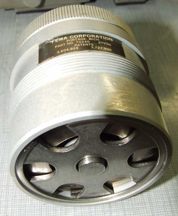
A total of 34 blades are a lot for a radial compressor of that size (just short of 150mm).
 |
In contrary to the previous engine(s) - WR2-6 -, the hub of the compressor is MUCH stronger.
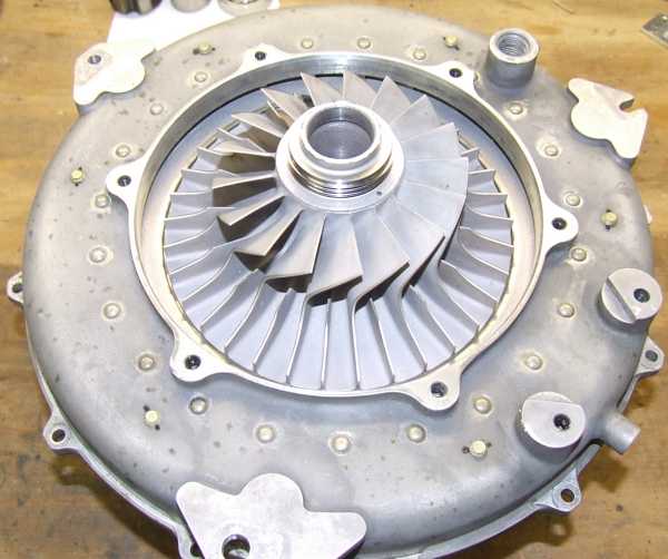 |
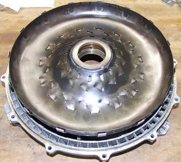
The radial compressor placed inside the diffuser housing.
 |
The radial compressor diffuser housing without the compressor. Once again, theres slight surface corrosion present in this area, but ists basically just surface discoloration. No material loss can be found.
 |
A close-up of the radial diffuser vanes. Due to the shallow angle its hard to tell the shape of the vanes, but using a soft wire to feel the shape lets me assume that the vanes are of the wedge type, but Im not 100% sure of this.
 |
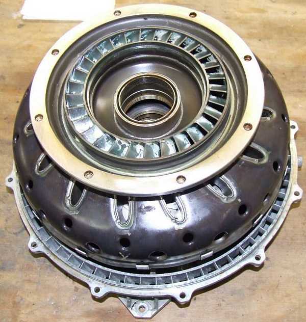
Here the axial diffuser/flow straightener vanes are visible from the rear of the diffuser housing.
 |
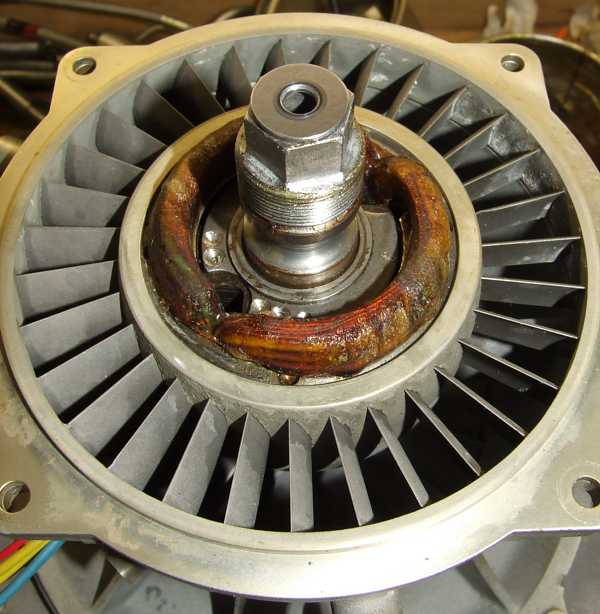
Thats the central labyrinth seal that is placed between the radial compressor rotor and the combustion chamber. It also ducts compressor air to the cooling channels inside the rotor shaft.
 |
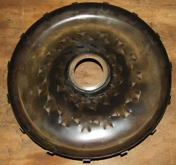
The front of the combustor with the heat shield. Its amazing how small the clearance is for the inrushing primary combustion air.
 |
The combustor front viewed from the compressor side.
 |
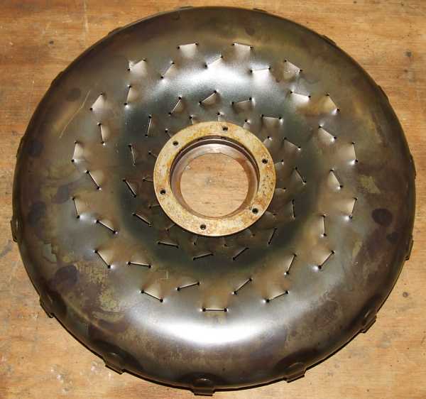
And here the flame side of the combustor is shown. This part is of rather simple construction, just a pressed sheet metal part/welded cosntruction with the primary air slots stamped/pressed into. Yet I guess, this simple part was the result of many hours of testing and experimenting.
 |
This photo is a close-up of the fuel injector section of the turbine shaft. The tangetial bores duct cooling air from the central labyrinth seal into the hollow shaft and to the aft combustor labyrinth seal.
 |
This sketch displays how the fuel is ducted through the hollow shaft and into the combustor.
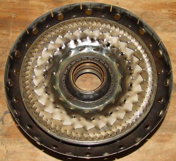 |
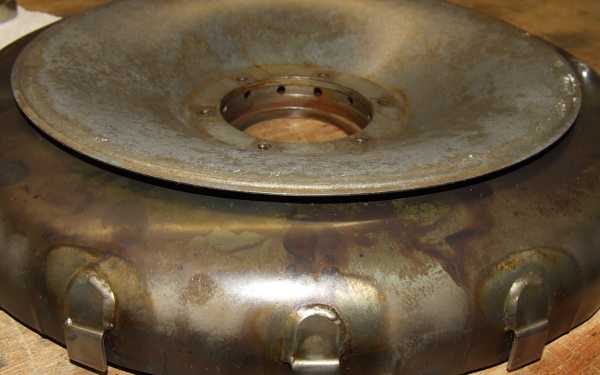
Thats a mighty complex part, an integral cast/welded/brazed/machined construction that forms the rear combustor liner, the aft combustor labyrinth seal, the hot air duct to the turbine nozzle guide vanes (NGV), the hollow pre-swirl vanes and air ducts to the rear of the combustor, and finally the NGV itself. I guess if this component has to be replaced, things get expensive ;-).
 |
Thats a view of the NGV side of the assembly, also the labyrinth seal is clearly visible.
 |
This photo shows the hollow pre-swirl vanes and the dilution air holes just in front of the bend to the NGV. Its quite amazing that the whole combustor / NGV section of this engine is 100% identical with the corresponding parts of the WR2-6!
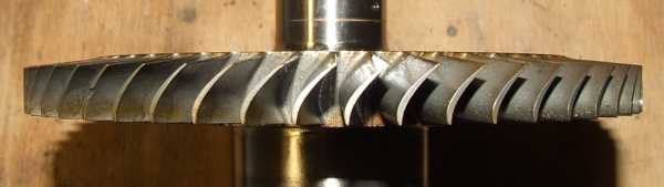 |
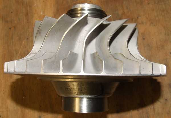
The turbine wheel is a precision cast component and - just like the compressor - has MANY blades -- 53 if I remember correcly. It is permanently attached to the shaft, probably by electron beam welding.
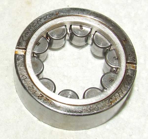 |
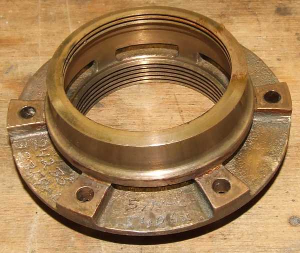
The rear bearing is of the cylindrical roller type and once again, is of very high quality. The slots in the outer race mate with an alignment pin in the turbine bearing labyrinth seal that keeps the outer race of the bearing from rotating.
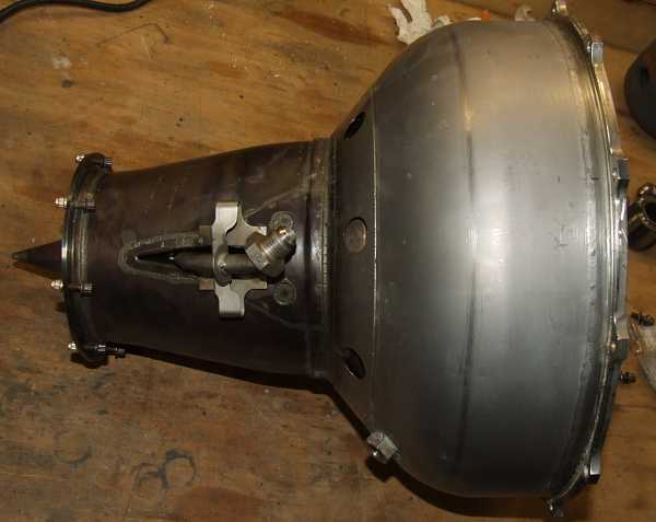 |
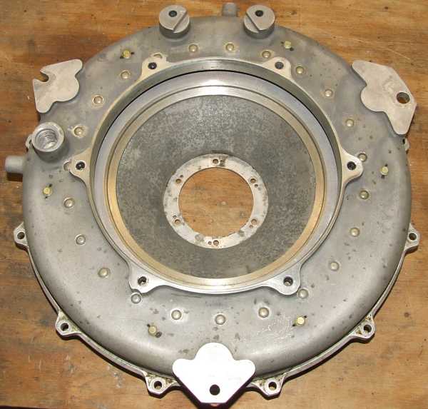
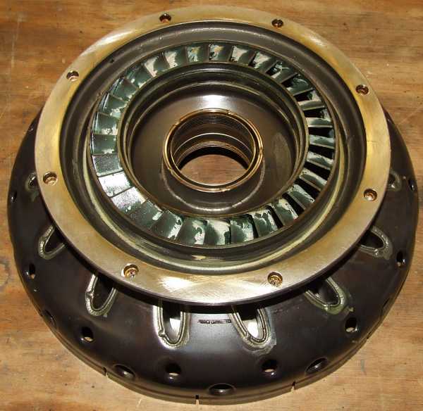
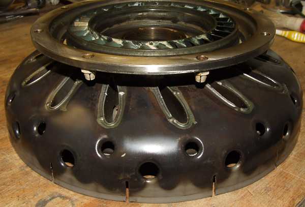
The combustor casing is a structural part of the engine and contains the rear bearing seat. This is also a very complex assembly of various pressed/stamped, cast and machined parts. Again, the components are welded/brazed together.
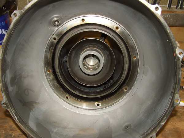 |
Here the turbine shroud and the bearing cavity are shown.
 |
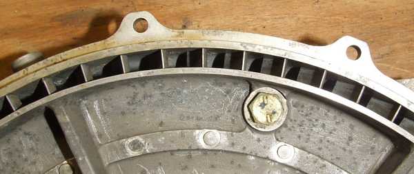
The inner wall of the bearing cavity is perforated to permit the oil mist that enters through the hole in the rear wall, to escape through the three hollow struts that center the bearing seat inside the turbine shroud.
 |
Thats the rear bearing labyrinth seal that basically prevents the hot exhaust gas behind the turbine wheel from entering the bearing cavity.
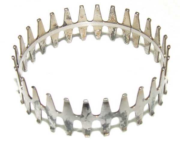 |
Thats the last shot of the walk through the engine and reassembly of the unit will commence afterwards. Its the rear bearing outer race vibration damper, a formed/ground spring steel part that centers the outer race of the roller bearing inside the bearing cavity while it still allows for a small amount of elastic radial displacement and angular alignment.
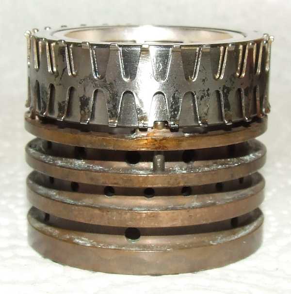 |
This photo shows the labyrinth seal/vibration damper/roller bearing stack as its supposed to be slided into the bearing cavity. Notice the alignment pin in the labyrinth seal mating with the slot in the bearings outer race.
 |
The central labyrinth seal aligns the combustor front with the heat shield and the diffuser housing.
 |
The front of the combustor is in place.
 |
The rear of the combustor has to be placed on the forward assembly while the hole for the spark plug has to be in the proper position and the slots have to mate with the sheet metal brackets. Well, finally everything is properly positioned...
 |
The rear bearing section is put back together. A circlip holds the complete assembly in place.
 |
The radial compressor impeller has been heated and slided onto the shaft. Since its an interference fit, just pressing the impeller home would result in scoring of the bore and thus weakening of the whole structure.
 |
The four-point bearings outer race is in place.
 |
The radial compressor cover/bearing seat assembly has been put back in place and the alternator rotor is already slided onto the shaft.
 |
Here the axial compressor stator and alternator assembly has been returned into the proper position.Notice the carbon seals rotating member of the fuel seal assembly.
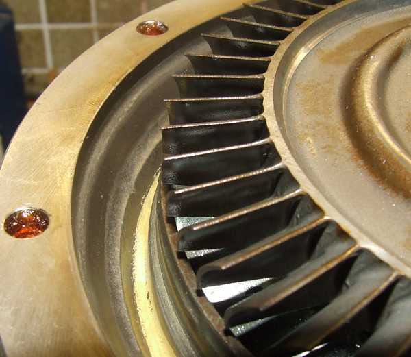 |
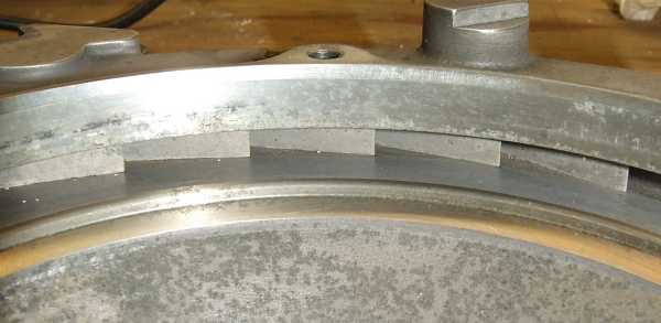
This photo shows how much bigger actually the turbine wheel is compared to the NGV shroud. The blades project by at least 2mm radially. Supposedly, this helps to reduce clearance losses at the turbine wheel periphery. Yet, this tends to increase turbulence losses at the step. Well, I guess theres no such thing as a free lunch... ;-)
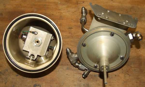 |
Thats the oil mist generator (OMG) opened.
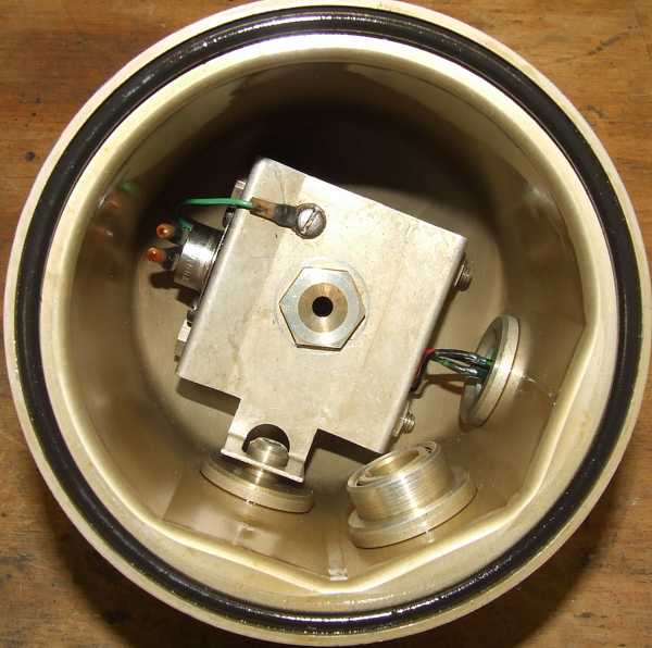 |
The lower section forms the oil tank and contains a drain port and the oil heater and thermostate switch. The heater will be activated if the engine has to be started at very low temperatures when the viscosity of the oil may be too high to produce a sufficiently fine oil mist.
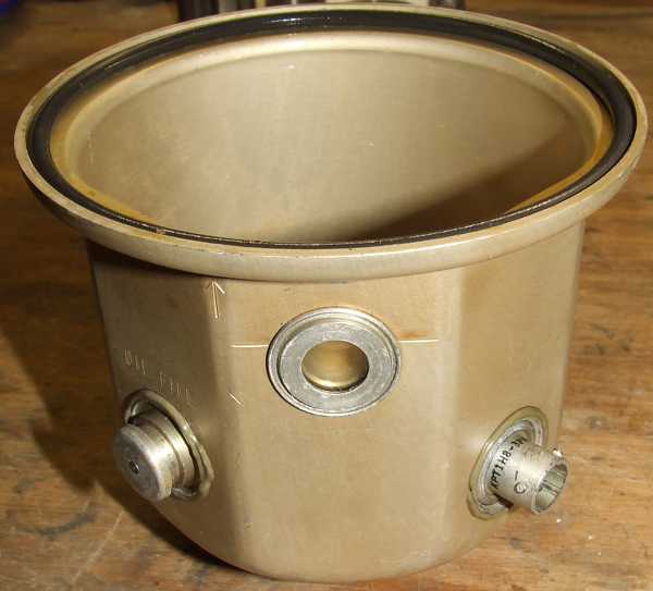 |
The left port is the oil filling valve, in the centre of the photos the sight glass is shown that permits checking the oil level.
 |
The tube pointing to the left ducts the oil from the tank to the atomization venturi.
 |
 |
Through the small nozzle at the base of the feed tube, the oil mist is ejected into the upper OMG cavity. All droplets bigger than a certain limit will settle on the metal parts or the baffle and drain back into the oil tank
 |
Only the droplets that are small enough will enter the port opposite of the compressor delivery air input and enter the lubration system of the engine. Below, one of the compressor bleed air metering orifices is shown.
 |
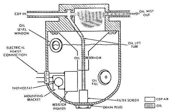 |
This sketch shows the operation of the OMG.
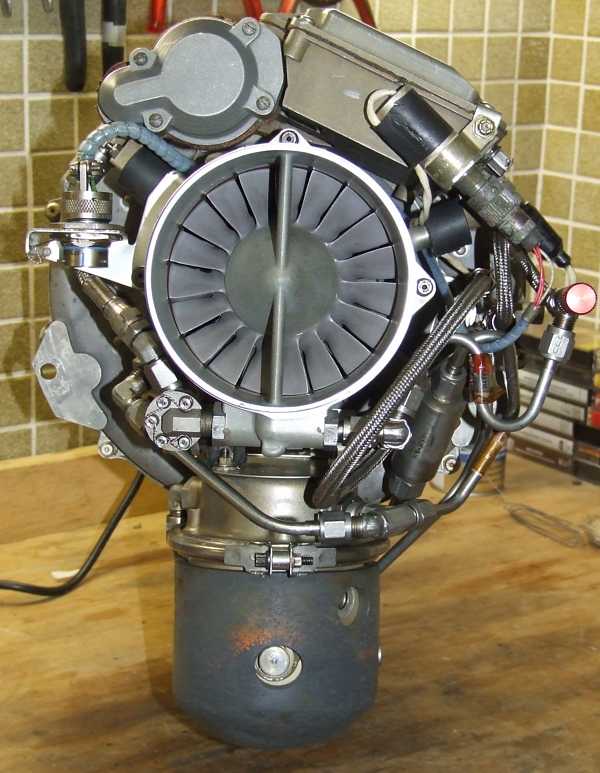
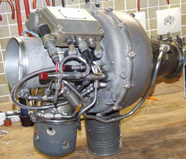
Finally the engine is back together in one piece. Enjoy the views from all sides...
 |
 |
 |
 |
 |
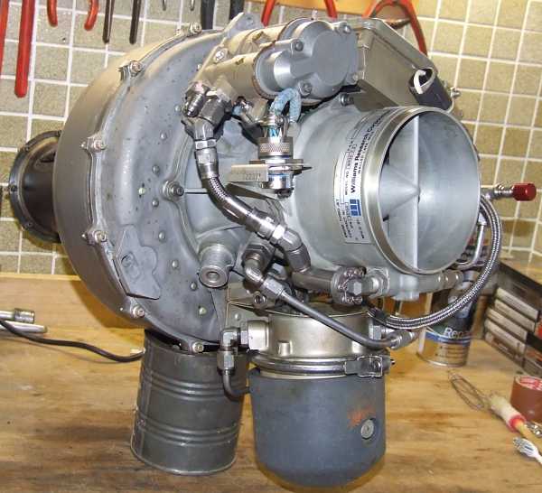 |
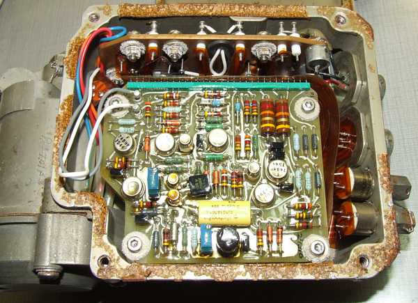
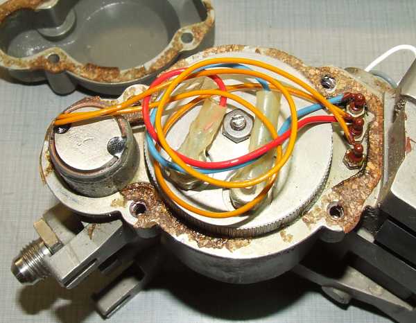
The last photos show the electronic fuel control unit. Actually, thats a spare one that suffered from some corrosion. The hardware appears to be a vintage 1975 electronic assembly and was quite advanced for that time. The unit basically consists of an electronic contol section, a proportional valve and a fuel shutoff valve. The control scheme is as simple as possible: The ECU is powered by a 24VDC supply and receives the engine the alternator frequncy (which is proportional to the engine RPM) as the only feedback signal. One trim-up and one trim-down signal are required to control the engine. But lets first look at some obsolete high-quality electronics...
 |
 |
 |
 |
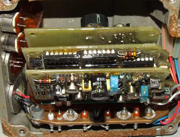 |
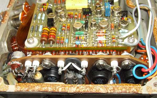
The whole electronic assembly consists of a stack of three PCBs and a manually wired power section behind. The individual PCBs and the power section are interconnected by a flexible capton printed circuit film.
The startup sequence is as follows: At the same time, the starting air and the ignition exciter are energized. When the engine exceeds 10,000 RPM, A trim up is signalled, causing it to launch the start sequence. The engine is slowly accelerated to idle RPM while the starting air source and the ignition exciter can be removed at around 40,000 RPM. Once 50.000 RPM idle has been reached, the engine can be controlled by signals to the trim up/down inputs.
 |
The big round part is the proportional valve while the smaller part is the fuel shutoff valve.
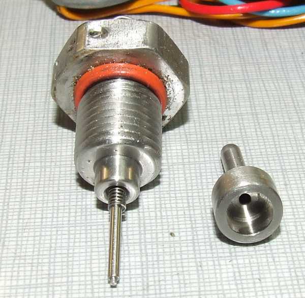 |
This needle/piston assembly actually hydromechanically dampens the proportional valve. Moreover, the threaded insert permits adjustment of the minimum flow to prevent an engine flameout when throttling down quickly.
 |
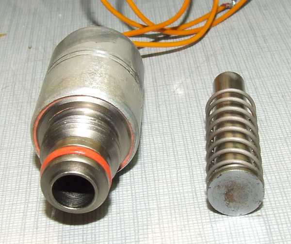 |
The fuel shutoff valve. Should go anything wrong with the engine, (speed excursions), the ECU will stop the enigne by closing this valve.
 |
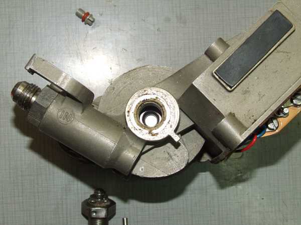
The proportional valve actuator and the shutoff valve plunger seat.
 |
 |
The mating surface of the proportional valve.
Meanwhile, a test stand for the engine has been welded, and I hope soon I can publish a video of a WR24-7-2 running...
Early summer 2014: Well, this soon is something quite relative - these things always take much longer than anticipated. But finally, here you are:
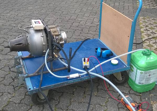 |
The engine professionally clamped onto a support... ;-)
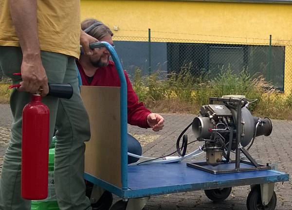 |
A fire extinguisher is something that I dont joke about - during firsts like this, it has to be present.
Since I arranged the fuel system a little different compared to the manufacturers design (I used a pressure-limited pump instead of utilizing the fuel cell pressurizing port of the engine), we had some trouble getting the engine to ignite and accelerate. The starting air caused too much back pressure in the fuel intake system so the pump couldnt provide enough flow. Thats why the engine rpm oscillated a little initially and then accelerated only up to approx. 36krpm (60%). Meanwhile, I changed the configuration as per the manufacturers specs and the engine accelerates flawlessly. Bot as yet, I havent got a video clip of that last configuration. Anyway, heres what Ive got. Enjoy!